


 Crane’s Sportsman Series shaft-mount rocker arms are ideal for high performance marine engines. The latest developments in advanced composite materials technology and metallurgy make it possible to eliminate the needle bearings. This is advantageous, because in the process of opening and closing the valves, the needles in traditional roller rocker arms physically roll in one direction as the valve opens, stop rotation at maximum valve lift and then, as the valve closes, reverse direction. This stopping and starting is referred to as bearing inertia, which consumes power and generates heat, particularly as engine RPM and spring loads increase. Further, the bearings in needle bearing rocker arms are described as full complement bearings, which means the needles lay against each other, again causing friction due to opposite direction of rotation of adjacent surfaces. One way to prevent this would be the use of so-called caged bearings, in which the needle bearings are separated. The problem with these, however, is increased weight and increased load on each individual bearing, because there would be fewer of them. Overcoming the problems with needle bearings has been a concern for many years.
The most common way to minimize bearing inertia is to reduce the diameter of the fulcrum shaft. Unfortunately, this creates at least three other problems, all of which are emphasized when valve spring load on the smaller shaft and bearings increases. This results in: (1) Increased friction (2) Increased shaft wear, and (3) Increased shaft flex, which can result in nose wheel chatter and accelerated valve guide wear. Anyone who has disassembled a needle bearing roller rocker that has been in use on a high performance marine engine will have noticed chatter marks on the fulcrum shaft.
One often repeated (and dubious) benefit of needle bearing roller rockers is that they require less oil for lubrication. This makes it possible to restrict oil flow to the top end, supposedly putting it to better use elsewhere in the engine. But with the use of high volume oil pumps and oil pans, or dry sump systems, there is more than enough oil available for lubrication. Furthermore in the marine application, top end oil is needed to help cool the valve springs.
To order a back issue call (800) 461-9128 or sign in to read entire article
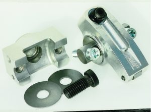 Crane Cams’ new Shaft-Mount Rockers have no needle bearings. Instead, they utilize an advanced composite bearing riding on a specially finished shaft of substantially larger diameter than needle bearing rocker arms. This delivers a rocker system with exceptional strength, zero bearing inertia and unequaled structural rigidity. They operate with less friction, deliver more horsepower, reduce valve guide wear, and have a longer operational life than any other rocker arm system. Additional power gains are also realized through the unique geometry of the rocker body design. Unlike other rocker arm systems, Crane shaft mounts lift the valve off the seat at a rate higher than the advertised rocker ratio. For example, a 1.70 ratio rocker opens the valve from the seat with a starting ratio of 1.80 to 1. As the valve is opening, the ratio reduces due to the geometry so that the stated 1.70 ratio is achieved at about 0.250” valve lift, and maintained throughout the remainder of the valve lift until the valve is within 0.250” of going back on the seat – at which point the ratio increases back to 1.80 to 1. The change of ratio occurs automatically due to the shape of the rocker body. This feature improves flow to the cylinder in this critical early period of the crankshaft rotation and helps maximize cylinder pressure and peak power. This unique action is not unlike changing to a more aggressive cam lobe profile while maintaining the same operational duration.
Crane shaft mount rockers are manufactured using CNC machinery and quality control verified continuously during all manufacturing operations.
Considerable strength and durability increases have also been realized by building these rockers from a new alloy of extruded aluminum billet material. This new alloy has far greater strength in the critical 250-300 degree temperature range seen by today’s high performance marine engines.
 Brodex Big Brodie aluminum heads will be used on this engine. The intake valves in these heads are 0.250” longer than stock because of the raised runners which promote better breathing. To mock up the valve train and to check V/P C, (valve to piston clearance) an intake and an exhaust valve were installed in one cylinder with low-tension checking springs. Then the head gasket and head was installed on the engine. Since the block was milled 0.008” and the camshaft being used has a little more lift and overlap than the original, the V/P C must be checked. The critical point for both intake and exhaust valves is the overlap period. The piston is still coming up on the exhaust stroke, the exhaust valve is closing and the intake valve is beginning to open. If you could see this taking place you would be concerned – will the exhaust valve close before the piston reaches TDC? Is the intake valve opening so fast it will hit the piston before it starts back down on the intake stroke? These events happen fast if the engine is being turned over by hand, when it’s running they would be only a blur. The tolerable minimum clearance between piston and valves is 0.100”. Valve-to-piston clearance should be checked five to ten degrees on either side of TDC, because in some instances (due to piston dwell and valve velocity) the valves may be in closer proximity to the piston when slightly off from TDC. In case of valve float due to over-revving, the exhaust valve is always the first to make contact with the piston. Since it is closing as the piston is rising, any discrepancy in following the dictates of the cam profile may cause contact with the piston.
A dial indicator is set up on the spring retainer of the intake valve and the V/P C of that valve checked; it’s over 0.100”. The dial indicator is moved to the exhaust valve and the V/P C checked, it’s also over 0.100” so we’re good to go in this respect.
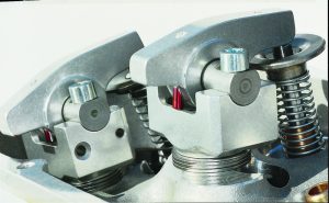
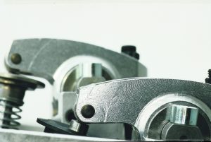
A pair of lifters are placed on the camshaft for one cylinder and the exhaust rocker stand and geometry-checking fixture installed with an adjustable pushrod and the rocker stand shimmed to the correct height. Then a rocker arm is installed with the adjustment screw turned out one complete turn to check the nose wheel travel across the valve stem tip as it opens and closes. These rocker arms should be run with adjustment screw no more than two turns out from seated position. This is required to achieve proper operational geometry, assure adequate internal oiling to the composite bearings, and minimize wear on pushrod seat and valve stem tip. This engine is equipped with a Crane hydraulic roller camshaft and kit, the adjustment screw is one turn out from fully seated to provide lifter preload. The adjustment screw threads are 24 pitch, when the screw is turned out one turn the plunger in the lifter will be depressed 0.0417”. The exhaust rocker arm geometry comes out perfect with three 0.060” shims and one 0.030” shim under the stand. With a dial indicator set up on the intake valve retainer the pushrod length and stand height are experimented with until the point of peak lift is found. This provides the greatest area under the lift curve, thus maximizing performance and power. In order to reach this point on these heads the intake rocker stand had to be filed oblong and the stand bolt head ground down in order to move the stand back away from the valve 0.050”.
After the correct geometry is established, the stands, rocker arms and turnbuckles are installed, and the turnbuckles adjusted to align the nose wheel on the valve stem. Then the shaft and rocker arm removed, the stand bolts taken out, blue Loctite applied to the threads and the bolts torqued to specifications, (60-65 lb/ft for aluminum heads). Before final assembly, apply the supplied assembly lube liberally to the seat adjuster threads, rocker shaft and nose wheel. Install the pushrods and bolt the rocker/shaft assemblies to the stands and torque to 25-28 lb/ft. Adjust the valves according to the specification card received with the cam, starting with the lifters for number one cylinder on the base circle of the camshaft. Proceed through the firing order rotating the crankshaft 90 degrees between each adjustment, (jam nut torque is 22-24 lb/ft). Prime the oil pump with a drill motor while the engine is being rotated by hand until oil is seen coming out of all of the rockers at the shafts or nose wheel area. This rocker arm system cannot be operated with restrictors in the oiling passages to the lifters or the rocker arms.
There are many advantages to Crane Cams shaft-mount rocker arms. They can be installed on an engine without having to remove the heads, and any clearancing necessary can be done with a die grinder. Extra tall valve covers are not required as with stud girdles, which are a real hassle every time the valves need to be adjusted. They will provide convenient, trouble free valve train stability so necessary in high performance marine engines.
 Price Turner was born into a boating family. He took an interest in engines at an early age, helping his father, who was always seeking better performance from his own and customers’ boats. Price began racing boats at 13 and opened a speed shop after high school. Following college, he started drag racing, working his way up to Top Fuel and setting numerous records. Along the way, he performed most of his own engine work and later attended marine technical schools. Price founded Clayton, New York-based Perfection Engine and continues to specialize in high-performance marine engines and engine upgrades. He won the 1000 Islands Poker Run in 1998 driving for Team Velocity. Price can be contacted at (315) 686-5331.


